



Phone:
0086 28 87573647
+86 19150187139

Abstract: This paper introduces failure detection and control methods for commonly used fixed-bed ion exchange desalination processors based on a single-stage multi-bed desalination system, and proposes improvement measures.
Keywords: Ion exchange, Water quality, Adsorption, Failure, Leakage, Control
The simplest process for ion exchange desalination is a single-stage multi-bed desalination system consisting of a cation exchange bed and anion exchange bed. Some single-stage multi-bed desalination systems adopt a unit system, meaning each system includes one cation exchange bed, one decarbonator, and one anion exchange bed. During operation, regardless of whether the cation exchange bed or the anion exchange bed fails first, they are regenerated simultaneously. Other single-stage multi-bed desalination systems use a master system, where cation exchange beds or anion exchange beds operate in parallel, and the exchanger that fails is regenerated.
1. Detection and Control Principles
The adsorption order of various cations in water by the strongly acidic cation exchanger is: Fe3+>Al3+>Ca2+>Mg2+>Na+>H+. Therefore, the adsorption capacity of the metal ion Na+ in water is the weakest. During ion exchange, the various ion adsorption layers in the resin layer gradually shift downwards, and H+ is eventually replaced by other cations. When the protective layer is breached, the bottommost Na+ leaks first. Therefore, monitoring the failure of the cation exchanger is based on sodium leakage. The reaction equation is (A represents the metal cation, R is the resin group): An+ + nRH = RnA + n H+
HCO3- + H+ = H2O + CO2↑
The adsorption order of various anions in water by the strongly basic anion exchanger is: SO42-->NO3-->Cl-->OH-->HCO3-->HSiO3-. Therefore, it can be seen that HSiO3- has the weakest adsorption capacity. During ion exchange, the various ion adsorption layers in the resin layer gradually move downwards, and OH- is replaced by other anions. When the protective layer is penetrated, the bottommost HSiO3- leaks first. Therefore, monitoring the failure of the anion exchanger is based on silicon leakage. The reaction equation is (B represents the acid radical anion, R is the resin group):
Bm- + mROH = RmB + mOH-
2. Control Points and Control Methods
Since the main pipe system includes a unit system and has advantages such as full resin utilization, improved exchanger effluent capacity, and reduced acid and alkali consumption, our research mainly discusses the ion exchange demineralized water treatment system based on this structure.
Taking the pure water station in the protein separation workshop of Chengdu Institute of Biological Products as an example, this system is a mainline water treatment system. The system structure is: sand filtration—activated carbon filtration—coarse filtration—cationized bed—primary anion exchange—secondary anion exchange—mixed bed—fine filtration—pure water tank. The system's water production capacity is 5 t/h. In the system's failure control research, we proposed the concept of unit failure control, which fully utilizes the advantages of the mainline water treatment system to control system failures.
The following are some data from the primary anion exchange (i.e., 1.1 anion exchange) of the first water treatment unit in this workshop during one operating cycle:
Table 1: Partial Data from the Primary Anion Exchange Operating Cycle
Water supply ion column | Electrical conductivity (μS/cm) | Water supply ion column | Electrical conductivity (μS/cm) | ||
1.1 Yang - 1.1 Yin | 4.99 | 1.1 Yang - 1.1 Yin | 3.00 | ||
1.1 Yang - 1.1 Yin | 4.47 | 1.1 Yang - 1.1 Yin | 3.05 | ||
1.1 Yang - 1.1 Yin | 3.59 | 1.1 Yang - 1.1 Yin | 3.09 | ||
1.1 Yang - 1.1 Yin | 3.30 | 1.1 Yang - 1.1 Yin | 2.57 | ||
1.1 Yang - 1.1 Yin | 3.27 | 1.1 Yang - 1.1 Yin | 2.22 | ||
1.1 Yang - 1.1 Yin | 3.26 | 1.1 Yang - 1.1 Yin (2.1 Yang - 1.1 Yin) | 4.93 (4.05) | 1.1 positive result failed (use 2.1 positive result). | |
1.1 Yang - 1.1 Yin | 3.15 | 2.1 positive - 1.1 negative | 3.52 | ||
1.1 Yang - 1.1 Yin | 2.89 | 2.1 positive - 1.1 negative | 3.44 | ||
1.1 Yang - 1.1 Yin | 3.80 | 2.1 positive - 1.1 negative | 2.28 | ||
1.1 Yang - 1.1 Yin | 3.82 | 2.1 positive - 1.1 negative | 2.16 | ||
1.1 Yang - 1.1 Yin | 3.68 | 2.1 positive - 1.1 negative | 2.03 | ||
1.1 Yang - 1.1 Yin | 3.13 | 2.1 positive - 1.1 negative | 5.12 | 1.1 Negative Failure | |
The above data are all actual operation records from the workshop. After supplying the effluent from the 1.1 anion exchange to the 1.2 anion exchange, the conductivity of the effluent is guaranteed to be below 3 μS/cm. Combined with the final mixed bed, the final effluent quality is consistently maintained between 0.1 μS/cm and 0.5 μS/cm. Based on the above data and the workshop's purified water test report, we performed standardized treatment (25 degrees Celsius, continuous operation) and plotted water quality curves under three different conditions (as shown below):
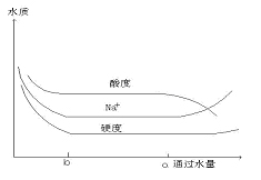
Figure 1. Effluent quality from the cation exchange bed
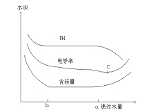
Figure 2. Effluent quality from the cation exchange bed
As can be seen from Figures 2 and 3: (1) The removal rate of various organic solutes by RO is greater than that by NF membrane. (2) The removal rates of different organic solutes are not the same, and some even differ greatly (for example, the absorbance removal rates of acetic acid by RO and NF membrane are 95.34% and 81.45%, respectively, while the absorbance removal rates of aniline are 61.50% and 46.82%, respectively).
3. Effluent Quality
After primary double-bed desalination, the conductivity (25℃) of the raw water is less than 10μS/cm, and the silicon content in the water is less than 100μg/L.
3.1 Cation Bed Effluent Quality
In Figure 1, the three curves before point b all drop rapidly, indicating that after the resin regeneration in the ion exchanger, the content of various impurities (acidity, sodium ion concentration, and hardness) in the effluent during the forward wash decreases rapidly. When the effluent quality reaches a certain standard (such as point b), it can be put into operation. Therefore, during the operation of section ba, the effluent from the cation exchange bed is acidic, and this acidity changes slowly. At point a, cations begin to penetrate the cation exchange bed. Based on the ion exchange activity, sodium ions are the first to leak out. In a desalination system, to remove all cations except H+ from the water, the strongly acidic ion exchanger must stop operating when sodium leakage occurs (generally, the acidity of the effluent is close to neutral at this point) and undergo regeneration, as shown at point a in Figure 1. This point is the sodium ion penetration point.
3.2 Anion Exchange Bed Effluent Quality
Since the anion exchange bed is always the downstream stage of the cation exchange bed in the ion exchange desalination system, the water quality changes in the anion exchanger fall into two categories:
① Anion exchange bed effluent quality when the cation exchange bed is operating normally and the anion exchange bed fails first: The anion exchange bed effluent quality is shown in Figure 2. Before point b, the curves drop rapidly, indicating that during the regeneration and forward washing, impurities in the water decrease rapidly until the operating effluent quality standard is reached. The ba range represents the stable exchange operation period, with an effluent pH of 7-9, conductivity <5μS/cm, and silicon content (as SiO2) of 20-50μg/L. After reaching point a, the anion exchange bed begins to fail, but the cation exchange bed continues to operate normally. At this time, the pH of the anion exchange bed decreases due to acid leakage; simultaneously, the silicon content and conductivity in the anion exchange bed effluent increase.
② Anion exchange bed effluent quality when the cation exchange bed fails first:
As shown in Figure 3, when the combined bed system reaches point a, the cation exchange bed begins to fail, but the anion exchange bed continues to operate normally. At this point, the Na+ ions leaking from the cation exchange bed flow through the anion exchange bed, resulting in NaOH in the anion exchange bed effluent. This increases the pH value of the effluent and interferes with the adsorption of HSiO3- by the strongly alkaline anion exchange resin, thus increasing the silicon content of the effluent. The reaction is: RHSiO3 + NaOH = ROH + NaHSiO3
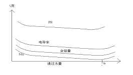
Figure 3: Effluent quality of the anion exchanger when the cation exchanger fails first.
4. Conclusions and Improvement Methods
(1) When the cation exchanger is close to failure, the Na+ content in the water gradually increases, thus affecting the anion exchanger. In industries where the requirements for purified water quality are not very high (such as the pharmaceutical industry), the failure of the cation exchanger can be controlled by adjusting the acidity of the cation exchanger effluent (mother pipe) and the conductivity of the anion exchanger effluent (first-stage secondary bed). Since CO2 is dissolved in the cation exchanger permeate and enters the anion exchanger without being removed, it reacts with OH- in the anion exchanger, affecting its processing capacity. Therefore, a carbon removal device can be installed between the cation and anion exchanges.
(2) Since HCO3- is generally removed in the cation exchanger, and conductivity is sensitive to OH-, the failure of the anion exchanger can be controlled by detecting the conductivity of the anion exchanger effluent in industries where silicon is not a detection item (such as the pharmaceutical industry). (3) Silicon leakage in ion exchange is a global problem. Practice has shown that the use of a dual-anion bed + mixed bed ion exchange system is very effective in controlling silicon leakage.
References
[1] China Biological Products Regulations, 2000 Edition
[2] National Standard of the People's Republic of China, GB/T11446.1-1997, Specifications and Test Methods for Electronic Grade Water
[3] Wen Ruimei and Wang Zaizhong, eds., Preparation and Testing Technology of High Purity Water, Science Press, 1999, Beijing
[4] Zhou Bensheng, Industrial Water Treatment Technology, Chemical Industry Press